Controlled Pressure
Reduces source pressure to a controlled downstream condition.
Equipment / Gas panels
Engineered gas control panels for pressure reduction, isolation, monitoring, purging and reliable gas delivery. PES designs and assembles gas panels for industrial, process, specialty and high-purity gas applications. Panel configuration is selected around gas type, source pressure, required delivery pressure, flow and point-of-use requirements.
Integrated control
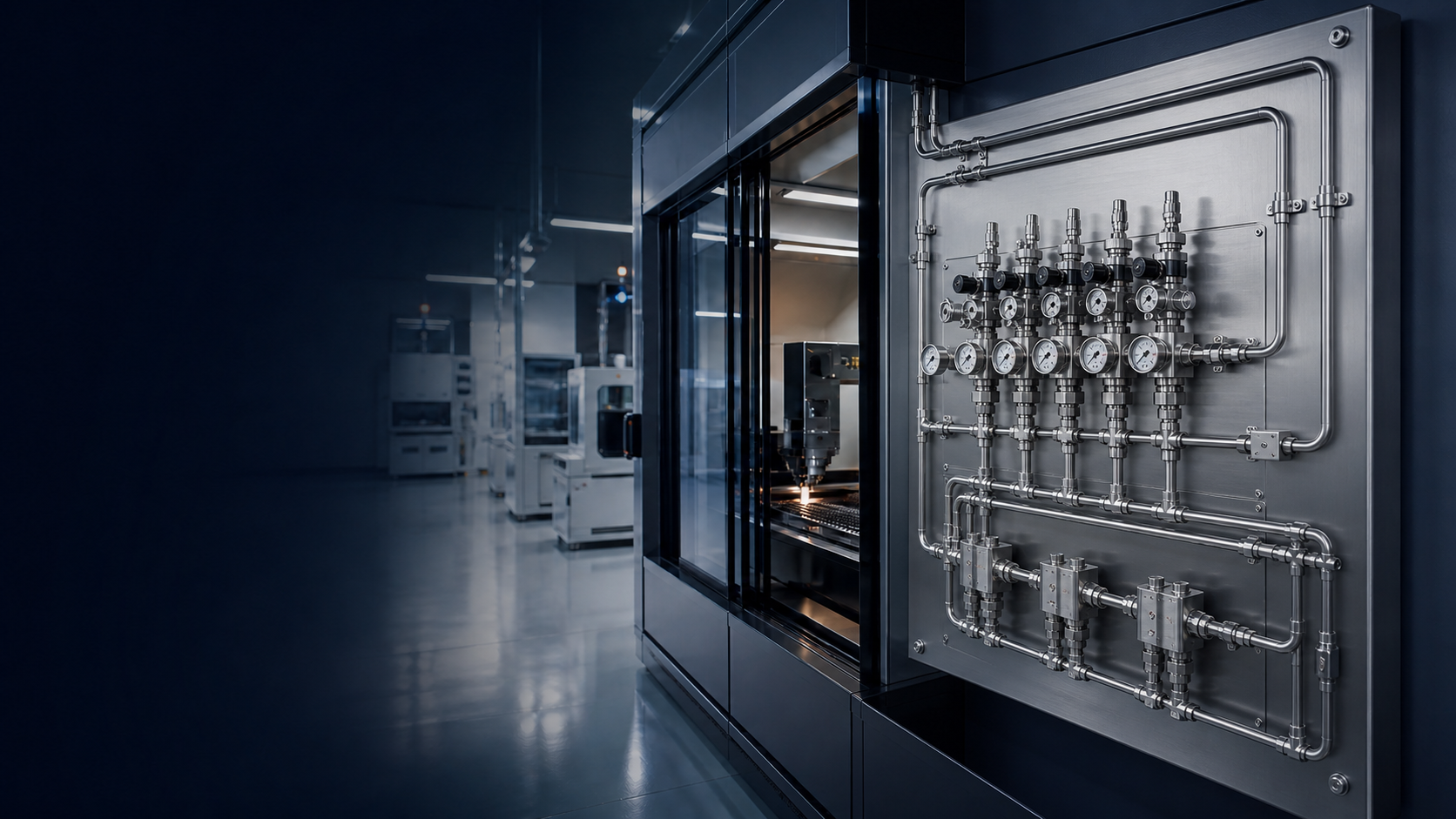
A gas panel is an assembled gas-control subsystem combining pressure regulation, isolation, instrumentation and, where required, venting, purging, relief or changeover functions.
The panel may be installed near the cylinder or manifold, close to a bulk source, at the beginning of a distribution network, near process equipment or at the point of use. It creates an organized, inspectable interface between the gas source and the application.
A gas panel is configured according to the gas service and application; there is no universal gas-panel configuration.
Reduces source pressure to a controlled downstream condition.
Separates sources and sections during operation or maintenance.
Supports gauges, switches or transmitters where required.
Provides controlled purge or vent functions for selected services.
Selection depends on gas classification, pressure, flow, purity, continuity and the control functions required by the application.
Single-stage panels use one reduction stage and may suit selected industrial inert, welding or utility applications. Two-stage panels add a second regulation stage where inlet variation, outlet stability or process sensitivity makes additional control appropriate. High source pressure alone does not automatically require two stages.
Changeover arrangements manage multiple source banks. Automatic systems switch according to configured regulator setpoints; semi-automatic systems may still require operator cylinder replacement or reset.
These prioritize suitable materials, internal cleanliness, low dead volume, connection design, controlled assembly, purging and leak integrity for electronics, pharmaceutical, analytical and research applications.
Toxic, corrosive, flammable, pyrophoric and reactive services may require isolation, purge, vent, detection, exhaust or enclosure interfaces. A panel alone does not make hazardous gas handling safe.
Installed near equipment, these panels can combine isolation, filtration, final pressure regulation, gauges and outlet connections according to equipment requirements.
A custom arrangement integrates only the required regulators, valves, gauges, filters, relief, purge, vent, tubing, fittings and monitoring functions.
A panel is not selected simply because source pressure is high. The design follows source pressure, required outlet pressure, flow, gas properties, stability, purity and safety requirements.
Single-stage regulation may be suitable where the regulator can handle the pressure change and required stability. Two-stage regulation may be considered for sensitive processes or changing supply pressure. The decision remains application-dependent.
Some industrial compressed gases are supplied in approximately 200 bar or 300 bar classes, while other products have lower source pressures. Certain manufacturer panel families show primary pressures around 220 bar and outlet ranges around 2.5–14 bar. These are illustrative manufacturer-specific examples, not PES design ratings.
Inlet connections, flexible pigtails or hoses, isolation and check valves, regulators, gauges, switches, transmitters, relief valves, vent and purge valves, filters, tubing, fittings, mounting plates, labels and monitoring interfaces.
Stainless steel, brass, copper, PTFE, elastomers and special materials may be considered according to gas compatibility, pressure, temperature, purity and application. Stainless steel is not automatically suitable for every gas.
| Application situation | Example source condition | Possible panel configuration |
|---|---|---|
| Simple inert gas supply | Moderate source pressure | Single-stage panel |
| High-pressure cylinder | Approximately 200–300 bar class source | Primary regulation panel |
| Sensitive process | High source pressure and controlled delivery | Single or dual-stage, based on stability |
| Continuous supply | Multiple cylinder banks | Manual, semi-automatic or automatic changeover |
| High-purity gas | Specialty gas source | High-purity panel with clean purge design |
| Toxic or corrosive gas | Pressurized hazardous source | Purge, vent or hazardous-gas configuration |
| Point of use | Already-regulated distribution | Final isolation, filtration and regulation |
Gas-panel configuration must be selected according to gas properties, source pressure, required delivery pressure, flow, temperature, environment and applicable requirements. Hazardous, toxic, corrosive, flammable, pyrophoric and oxygen-service systems require appropriate engineering controls and qualified design and installation.
A manifold and gas panel are often complementary systems: the manifold aggregates sources, while the panel regulates, isolates and monitors delivery.
Gas, source, pressure, flow, purity and point-of-use requirements are reviewed.
Regulators, valves, instruments, materials and connections are selected for service.
Mounting, tubing, fittings, labels, purge and vent paths are organized for access.
Connections, valve operation, regulator function, leak integrity and required tests are verified.
Identification, records and commissioning information support installation and maintenance.
Send the available information below. Missing values can be developed as part of the technical review rather than assumed.
Gas name, mixture, purity, cylinder, bundle, bulk or process source, and number of banks.
Source pressure, outlet pressure, distribution pressure, normal flow, peak flow and points of use.
Single or reserve source, changeover preference, classification, purge, vent, detection and enclosure.
Cylinder, pipeline and equipment connections, indoor or outdoor location, existing lines and future expansion.
Values remain application-specific until the gas service, pressure, flow, connection and installation conditions have been reviewed.
Oxygen requires suitable, clean components. Hydrogen requires equipment suitable for hydrogen and its pressure and temperature conditions. Acetylene and fuel gases require gas-specific equipment, materials and pressure limitations. Nitrogen and argon may share broad architecture, but not necessarily identical component selections.
| Regulator | Gas Panel | Gas Manifold |
|---|---|---|
| Individual pressure-control component | Integrated control assembly | Multiple-source header arrangement |
| Controls pressure | Controls, isolates and monitors gas | Aggregates or selects sources |
| May suit simple applications | Can include purge, vent and changeover | Can feed a gas panel |
Available configurations and specifications vary according to gas service, pressure requirements and application.
| Specification | Available Options |
|---|---|
| Gas service / classification | O₂, N₂, Ar, CO₂, He, H₂, specialty or mixed gas; inert, oxidizing, flammable, toxic, corrosive or pyrophoric |
| Source / number of sources | Cylinder, bundle, bulk or process source; single or multiple banks |
| Pressure / flow | Inlet pressure, outlet pressure and normal or peak flow are application-specific |
| Regulation / changeover | Single-stage or two-stage; none, manual, semi-automatic or automatic changeover |
| Material / connections | Stainless steel, brass, copper or special material; NPT, BSP, tube or gas-specific connections |
| Instrumentation | Gauge, pressure switch, transmitter, relief protection and monitoring interface as required |
| Purge / vent / mounting | None or application-specific; open panel, wall, skid or cabinet mounting |
Related: Gas Regulators · Gas Manifolds · Valves
Share gas type, pressure, flow, points of use and site conditions with the engineering team.